Some of the most interesting parts of the learning process during the past 10 weeks are the 'discoveries' made while following expected or predicted paths. Some of these unexpected insights include:
- The rich practical history of cinematography through the use of different kinds of light, configurations, compositions and storytelling.
- Benchmarking monochromatic, single-light photography of geometric solids and realizing that the lighting of surfaces in reality is markedly different from traditional visualization formulae learned in design school.
- Observing from photography that some of the most interesting details of a surface may be not the ones in direct light but rather in shade or cast shadows.
- The complexity of shadows generated by one single light source but varied by reflections from the object itself or by neighboring objects.
- Shaded surfaces or cast shadows that act similarly to or are affected similarly by rim lights in pushing objects off the page depending on composition and contrast.
- The complexity of the Maya software and understanding its capability.
- Entering this independent study with a certain set of expectations and finishing with a different set based on what I learned is versus isn't important. In this case, knowing in the beginning how to illuminate an object on paper using a formula for casting shadows, highlights, and shading may be less essential to learn than simply the power of observation for the individual designer. The latter enables the designer to learn the basics on their own instead of relying on an instructor.
The next stage of investigation should probably include:
- Further photographic studies of still-life compositions and generating Maya modeling and realistic rendering to match. This will help to begin documentation of the process of quantifying product lighting protocol for 3D modeling.
- Completing documentation of narrated slide/mpeg instruction for casting shadows of various objects beginning with geometric solids and progressing to more complex surfaces.
- Establishing draft outline and processes for combining photographic documentation, design visualization, and 3d modeling/lighting of specific solids and surfaces. This concurrent study is intended to enable the student to develop their own system of observation and visualization that might be self-correcting given a custom tool palette.
- Emphasizing development of a system of self-education versus rote memorization.
- Building a visual narrative of design visualization including all systems used in both education and professional practice settings to help young designers understand the breadth of educational requirements as well as possibilities for this aspect of the design process. Ideally, this storyboard would inspire the viewer to take initiative in finding that niche of the profession he or she would most want to investigate and learn.
Wednesday, August 24, 2011
Monday, August 15, 2011
Observations of reflected light with a single light source
During the process of set-up and photography of the four geometric solids in the studio, it became apparent that, even with just one light source, the phenomenon of light reflecting off direct and indirect surfaces into other areas became a significant feature.
Although the practice of cinematography and theatrical lighting utilizes techniques to place light strategically and accurately, the challenge of understanding and manipulating the effects of light with just a single source has offered some unexpected insights for me.
Attached are a series of photographs with the same four solids composed in a variety of configurations exhibiting some different results. Included first are single images of the solids on the ground plane surface as benchmarks for shading and cast shadows.
 |
| Fig.01 - Geometric solids with same single light source |
 |
| Fig.02 - Original composition with light source from left instead of right |
 |
| Fig.03 - Note the variation in value of cast shadows on different surfaces |
 |
| Fig.04 - Note the variation of surface light on the sphere in the shading and cast shadows |
 |
| Fig.05 - Although appearing randomly composed, this image's value lies in the form definition revealed in shaded and reflected surfaces |
In the beginning of this project, I assumed that the strongest methodology for modeling three dimensions would focus on a definitive light source using highlights and cast shadows to create contrast. With a background in drawing and design visualization I was surprised by the reduced evidence of edge highlights and surface definition in directly illuminated surfaces. Instead, a much richer variety of light modulation appears to exist in the shading and cast shadows where ambient and reflected light from adjacent surfaces provide softer but distinctive definition.
One of the unintended gains from the photo session has been the revelations in reflected light from one object or surface to another using matte surfaces only. Often in the design process, designers may specify highly reflective surfaces for the product. The downsides to this methodology can be the masking of the true effects of light and the image complexity resulting from bounced reflections.
Lighting Geometric Solids - Refining 3d to coincide with studio lighting
The next step in defining the appropriate lighting configuration is to use the studio lighting image as a benchmark for adding to or adjusting the Maya lighting system.
The first image is the studio photograph followed by sequential changes to the 3d file.
The first image is the studio photograph followed by sequential changes to the 3d file.
 |
| Fig. 01 - Studio photo shoot |
 |
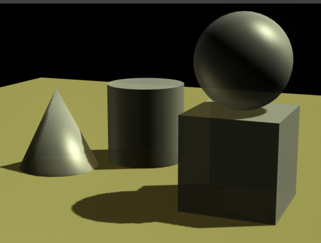
Fig. 02 - Incorrect reflected lighting on the underside of the sphere. |
 |
| Fig.03 - Boost the diffuse setting for better light rendition of surfaces and reorient light fill/reflect into underside of the sphere |
 |
Fig.04 - remove bounce light around outer receding surfaces |
| Fig.05 - Reduce the transparency of the surfaces to reflect more light |
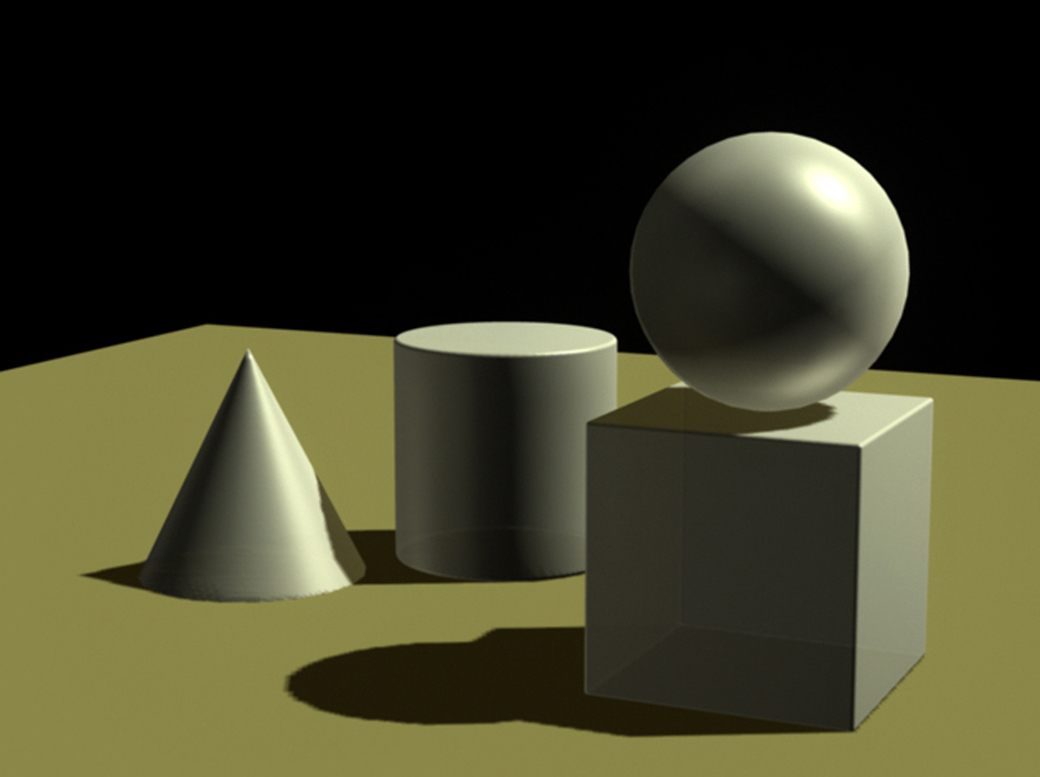 |
Fig.06 - Add rim light on left side of sphere to show reflections of cone and cylinder |
 |
| Fig.07 - Add light from cone reflecting into left side of cylinder |
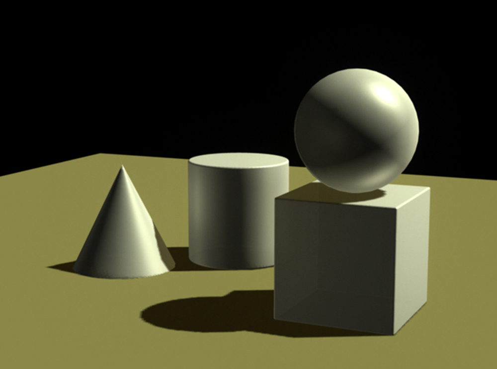 |
Fig.08 - Add light directly from the right to illuminate the cylinder, cone, and cube closer to the studio photograph |
 |
| Fig.09 - Increase resolution of cast shadows |
Sunday, August 14, 2011
Lighting geometric solids - coordinating 3d renderings with reality
The 3d renderings done in Maya prior to this were executed with a general knowledge of lighting from an industrial design education and practice perspective: establish a primary light source ("key light") in a position that illuminates important features of the object/product, casts shadows which help to define features and create a sense of visual depth, and provides secondary lighting to surfaces in shadows with reflected light.
Some assumptions can be made about secondary lighting: with the product resting on or near a ground plane, some light from the overhead primary source will reflect off that plane and up to surfaces in view; ambient light will help to illuminate surfaces in shade cast by the primary light; light from the far horizon is generally portrayed as indirect and cool in nature, illuminating receding surfaces and adding a cool hue to the color which, in turn, adds to visual depth. The earlier Roland Stickney rendering of a John Deere tractor illustrates these principles.
Translating these principles to a Maya image required a reasonable understanding of the software. The results were exhibited in the last posting:
 |
| Fig.01 |
Figure 01 shows geometric solids composed to take advantage of highlights and cast shadows to create a better sense of visual depth and object surface definition. The modeling, however, is still crude because the facets of the polygonal surfaces don't accurately portray real life. Revisions of these features helped to make the highlighted portion of the cone, for example, more realistic as shown in Figure 02 and 03. Addition of edge radii to the cube and cylinder integrated highlights enhancing the 3-dimensional aspects.
 |
| Fig.02 - before and after solids surface refinements |
 |
| Fig.03 - refinements to rendered surfaces and definition Figure 03 sets the stage for the next, essential step in the process of establishing benchmarks for the designer to understand and execute visualizations of illuminated products: photograph the same geometric solids in a studio setting to establish visual benchmarks to verify the logic and mechanics of a drawing system. |
Figure 04 is an image of the geometric solids composition photographed in a studio setting with one primary/key light but no ambient, rim, fill or reflected secondary lights.
 |
| Fig. 04 - studio lighting composition |
While the positioning of the objects and key light are close to the same as in the Maya composition the effects of the lighting are noticeably different. Regardless of the different color value of the computer versus real solids, the light reflected of the #2 surfaces (vertical surfaces facing the direction of the light) is significantly more. Light reflecting of the top plane of the cube into the underside of the sphere is significant. Ambient reflected light from the cone and cylinder into the left side of the sphere is less than indicated in Maya. The highlighted surface of the cone reflects considerable light into the left, shaded surface of the cylinder. Cast shadows vary widely depending on objects and respective illuminated or shaded surfaces in the background.
Refining the Maya light configurations will be the next step to more accurately represent the connection between studio lighting and the computer model.
Refining the Maya light configurations will be the next step to more accurately represent the connection between studio lighting and the computer model.
Monday, August 1, 2011
Maya - traditional lighting system for industrial design concept drawings - Step 01
A first stage to developing an integrating lighting system for industrial designers to use in both drawing and computer visualization would be to take advantage of the depth and breadth of knowledge in the profession of cinematography. As indicated in the last post, the number and range of capability of the different kinds of lights and light functions in theatre and film scenarios far exceed those necessary for the average industrial designer. Many designers are able to work with graphically-literate clients who don't require full-value and -color renderings to understand the concept. As a result, line drawings (or the proverbial napkin sketch) often suffice. Adding the complexity and time requirements of an accurate lighting system with shading and cast shadows in a concept drawing may not be worth the effort.
The equity in a system of the latter, however, is that the designer can never predict the client's reaction to an image, especially one rendered very convincingly by hand. The 'excitement' factor in a near-photographic drawing should never be underestimated. The magic of creating a realistic image by hand has never lost it's value in culture or commerce.
My hypothesis is that the principles of successful cinematographic product lighting with a single key light in Maya could help the ID visualizer understand and implement a powerful, if simple, lighting system on paper to accurately portray form and details of the specific concept. As Maria Palazzi, director of ACCAD, put it so succinctly, "Model with light."
The most recent steps in lighting the simple plane of geometric objects are now concerned, first, with a good composition and, second, with object-individualized key, fill, and bounce lights to create not just an interesting image but one that looks 'obvious' compared to a still life set-up with traditional theatre lighting. The objective is to avoid the hyper-realistic possiblities of too many lights, high levels of surface specularity, and unrealistic conditions and, instead, make an image we can relate to and establish a functional system analogy to help designers integrate the intricacies of successful lighting in their drawings.
Figure 01 shows a recent compostion with, now, several fill lights to bring reflected light into the shaded object features and cast shadows. Unless there is no light present, all surfaces and details will have some level of illumination and reflection.
 |
| Figure 01 Figure 02 shows a close-up of the image with the influence from the fill-lights. Surfaces formerly unseen in shadow are now more visible. Three-dimensional form is better contoured and represented. |
 |
| Figure 02 |
Subscribe to:
Posts (Atom)